
Post #1
|
Monday, 16-Jan 2017 @ 6:27pm
Hey All,
Have been working out the details over the last few months, but i have a solid plan (for now) so figured it was time to finally post a build thread for my 1000.
Ā
Ā
The plan as it stands is...
Ā
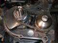
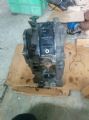
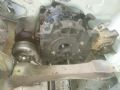
ENGINE:
single rotor 13bĀ
6 port end plates
9.7:1 compression lightened rotor
ITB'sĀ
tuned length intakes
EFI
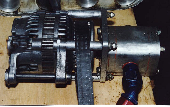
dry sump (mainly for fitting reasons, shown later)
Tension bolts re-drilled and tapped to suit M12 studs (will be clearance to act like dowels)
S1-3 5 speed rx7 gearbox
There will be heaps of other little things that will come up (ie porting) as i progress through I'm not 100% decided upon yet.
Ā
STEERING:
As i have no steering box, steering wheel or anything steering related I will be converting it to rack and pinion steering
Ā
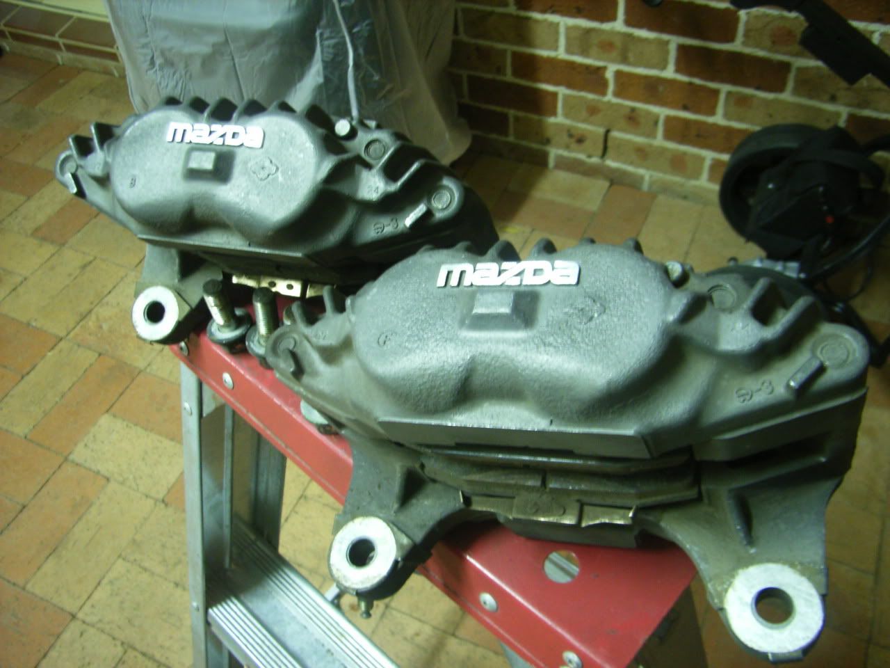
BRAKES:
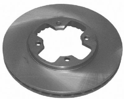
R32 GTS-T front, undecided on rotors (I want 2 peice but not sure if budget will stretch or enigneer will allow it)
S13/14/15 rear, again want 2 peice, but we'll see
Dual master cylinders
Ā
BODY:
usual rust repairs, etc
It had a light hit on the front so it needs pannel work to straighten the lights, lower lip fender and top radiator pannel.
Someone has also given the gearbox tunnel a good beating to fit a larger gearbox, but as i'll need to sut it out to fit an RX7 gearbox it's not a big issue (but one of the deciding factors in which car to race and which one to restore)
likely run lexan rear quarters as i only have 1x set of rear quarter glass (and they are heavy)
Ā
SUSPENSION:
I have no idea on this, looking for input from you guys.
Rear axle will likely be a shortened datsun 1200 ute, with AE86 LSD
Ā
ECU:
my proposed tuner like MicroTech, just waiting for a reply if it's able to do everything i want
CAN dash (ie racepack)
Ā
Enough text, everyone likes pics
Ā
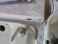
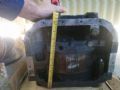
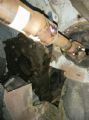
Scuttle pannel needs some work (most of what u see is seam filler)
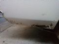
Rear quarters are also pretty average
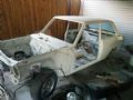
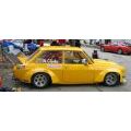
The car as I picked it up, note the lack of everything...
Ā
Ā
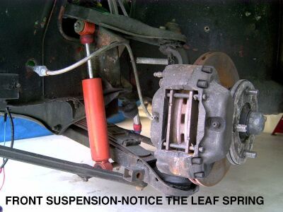
For the purists out there, I got 2x datsuns as part of the deal, although one (this one) was only a bare shell (no bolt on pannels) with front suspension. With the lack of availability of parts i decided that rather then cut up the shell for patch pannels (the original owners plan) i would turn this one into a track/weekend car and later on fully restore the other one.
Ā
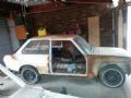
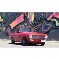
And for those wondering, this is the other one. A lot of surface rust, but much better shape then this one, although the drivers side floor requires replacing
Have been working out the details over the last few months, but i have a solid plan (for now) so figured it was time to finally post a build thread for my 1000.
Ā
Ā
The plan as it stands is...
Ā
ENGINE:
single rotor 13bĀ
6 port end plates
9.7:1 compression lightened rotor
ITB'sĀ
tuned length intakes
EFI
dry sump (mainly for fitting reasons, shown later)
Tension bolts re-drilled and tapped to suit M12 studs (will be clearance to act like dowels)
S1-3 5 speed rx7 gearbox
There will be heaps of other little things that will come up (ie porting) as i progress through I'm not 100% decided upon yet.
Ā
STEERING:
As i have no steering box, steering wheel or anything steering related I will be converting it to rack and pinion steering
Ā
BRAKES:
R32 GTS-T front, undecided on rotors (I want 2 peice but not sure if budget will stretch or enigneer will allow it)
S13/14/15 rear, again want 2 peice, but we'll see
Dual master cylinders
Ā
BODY:
usual rust repairs, etc
It had a light hit on the front so it needs pannel work to straighten the lights, lower lip fender and top radiator pannel.
Someone has also given the gearbox tunnel a good beating to fit a larger gearbox, but as i'll need to sut it out to fit an RX7 gearbox it's not a big issue (but one of the deciding factors in which car to race and which one to restore)
likely run lexan rear quarters as i only have 1x set of rear quarter glass (and they are heavy)
Ā
SUSPENSION:
I have no idea on this, looking for input from you guys.
Rear axle will likely be a shortened datsun 1200 ute, with AE86 LSD
Ā
ECU:
my proposed tuner like MicroTech, just waiting for a reply if it's able to do everything i want
CAN dash (ie racepack)
Ā
Enough text, everyone likes pics
Ā

Scuttle pannel needs some work (most of what u see is seam filler)

Rear quarters are also pretty average

The car as I picked it up, note the lack of everything...
Ā
Ā
For the purists out there, I got 2x datsuns as part of the deal, although one (this one) was only a bare shell (no bolt on pannels) with front suspension. With the lack of availability of parts i decided that rather then cut up the shell for patch pannels (the original owners plan) i would turn this one into a track/weekend car and later on fully restore the other one.
Ā
And for those wondering, this is the other one. A lot of surface rust, but much better shape then this one, although the drivers side floor requires replacing

Cheers
Luke
Luke


.jpg)
.jpg)

