44 Posts - Page: 1 | 2 | 3 | Next

2 door sedan 1000 build, single rotor goodness

Hey All,
Have been working out the details over the last few months, but i have a solid plan (for now) so figured it was time to finally post a build thread for my 1000.
 
 
The plan as it stands is...
 
ENGINE:
single rotor 13b 
6 port end plates
9.7:1 compression lightened rotor
ITB's 
tuned length intakes
EFI
dry sump (mainly for fitting reasons, shown later)
Tension bolts re-drilled and tapped to suit M12 studs (will be clearance to act like dowels)
S1-3 5 speed rx7 gearbox
There will be heaps of other little things that will come up (ie porting) as i progress through I'm not 100% decided upon yet.
 
STEERING:
As i have no steering box, steering wheel or anything steering related I will be converting it to rack and pinion steering
 
BRAKES:
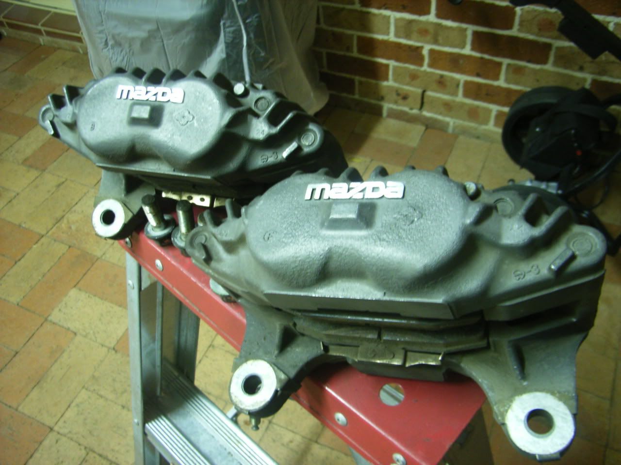
R32 GTS-T front, undecided on rotors (I want 2 peice but not sure if budget will stretch or enigneer will allow it)
S13/14/15 rear, again want 2 peice, but we'll see
Dual master cylinders
 
BODY:
usual rust repairs, etc
It had a light hit on the front so it needs pannel work to straighten the lights, lower lip fender and top radiator pannel.
Someone has also given the gearbox tunnel a good beating to fit a larger gearbox, but as i'll need to sut it out to fit an RX7 gearbox it's not a big issue (but one of the deciding factors in which car to race and which one to restore)
likely run lexan rear quarters as i only have 1x set of rear quarter glass (and they are heavy)
 
SUSPENSION:
I have no idea on this, looking for input from you guys.
Rear axle will likely be a shortened datsun 1200 ute, with AE86 LSD
 
ECU:
my proposed tuner like MicroTech, just waiting for a reply if it's able to do everything i want
CAN dash (ie racepack)
 
Enough text, everyone likes pics
 

Scuttle pannel needs some work (most of what u see is seam filler)

Rear quarters are also pretty average

The car as I picked it up, note the lack of everything...
 
 
For the purists out there, I got 2x datsuns as part of the deal, although one (this one) was only a bare shell (no bolt on pannels) with front suspension. With the lack of availability of parts i decided that rather then cut up the shell for patch pannels (the original owners plan) i would turn this one into a track/weekend car and later on fully restore the other one.
 
And for those wondering, this is the other one. A lot of surface rust, but much better shape then this one, although the drivers side floor requires replacing
Cheers
Luke
ENGINE 
I have the end plates, a housing and an early timing cover to start mocking up the engine positon, I'm hoping to source a gearbox this weekend so i can finalise positions
 
One of the main reasons for choosing the rotary was the ability to have the engine mounted behind the front cross member, for a true front mid engine car. This will also help with the weight distribution. 
One issue i ran into was the firewall sits right where the rear housing want to sit (see below). The reason, large timing cover (relative to the motor).


I can't reduce the size by much due to the oil pump location protrucing so far from the block.

So after a few weeks of looking on US ebay I found a suitable 3 stage dry sump pump that should allow me to machine a much smaller front timing cover allowing the engine to sit where I want it to be (although it will still be tight). It will also allow for a flat bottom potentially allowing a lower engine/gearbox mounting position, but that will depend on the location of the rack and pinion steering box.

 
Hoping that my M10x1 die will come in tomorrow so i can machine up some correct length M10x1 bolts to mock up the motor. I still need to source some factory dowels before i can start cleaning up oil/water passages and having the block machined for M12 studs
 
BRAKES
Mocked up R32 GTS-T brakes on the datsun 1000 hubs. I was going to use S13 sr20det brakes all round, but the R32's are 4 pot and lighter, only issue is I'll have to run 15's. I was planning on it for track use (more tyre selection and cheaper) but did want 14's for street duties...


Without modifying the hub or steering arm you couldn't fit a larger front brake. I'm hoping with good pads, fluid and discs it should work well at the track.
 
I attempted to get a 10mm plate between the disk and the drum brake mounting point, but it was just too tight. I have dropped the assembly off at a machine shop to fabricate a donut shaped plate that will fit on the back of the knuckle (I'll post photo's detailing the mods when i get it back)
 
Also picked up a pedal box, should be interesting to get it to work as it's a reverse swing type so that the master cylinders are inside the cabin. I didn't want to run into interference issues in the future with the master cylinders and intake, hence the reverse swing


I'm hoping to make a mounting plate on Wednesday after work, looking at using the original mounting area but choppin the ends of the C section away and re-enforcing it with gussets to the windshield pannel and fire wall (after applying strengthening plates). Again will post pics once i start cutting and fabricating.
 
BODY:
I managed to remove all of the sound deadening in the cabin, except for the transmission tunnel (as it'll likely be too small and have to be cut away) and the spray on stuff used in the rear quarters. I used dry ice for the cabin, anyone have any tips for the inside of the rear quarters (boot area)?
I also removed the box that feeds the heater box air as it was full of rust and holes. Just going to weld a plate under the grill to stop water/air coming in. I will be running an electric windscreen heater (basically a 12v hair dryer) so i don't have to run water lines or a heating unit.
 
Also forgot to mention that there is no boot floor left due to rust so a carbon pannel will cover the whole boot floor.
 
SUSPENSION:
Managed to find some upper and lower control arm bushes in Japan, so ordered them
Anyone have ideas for the other bushes? I was just going to get some machined out of polyerethane unless someone has a better idea?
 
Also going to the local wreckers this weeked to see if i can find a rack and pinion rack with centres between 430-440mm apart.
If I can't find one, does anyone have any recomendations for light rear steer racks that can be easily cut down?
 
Has anyone had any success with fibreglass leaf springs? Have read mixed reviews on 4x4 forums but nothing related to small lightweight dattos.
 
 
PARTS I REQUIRE
I'm chasing a 1200 ute rear axle
Front windscreen
if anyone has one for sale in the melboure-ish area let me know (or a source for a windscreen)
Cheers
Luke
great to hear this is still in the pipeline and some awesome ideas there!
the rear wheel well rust is a blessing I did the same to a lightweight sedan I had
and anywhere you can save weight is the key to kicking more hp & improve dynamics
 
The only thing that I would have suggested was moving the front suspension a few inches
forward and doing some custom guards and bonnet or total flip front as done on other 1000s
one in particular was in Adelaid some time back with excellent aero considered
The pic is somewhere on 1200.com blue and pink I think it was.
That would improve handling again, allow better wheel clearances on foot well and save
on dry sump unit as the rotary never needs them.
 
The tunnel is smaller than it should be, feel no shame in making it bigger as its smaller
than even corolla tunnels for same like K series boxes.
 
So no boost for this little critter? even as a single rotaries produce so much exhaust energy
its a shame not to take advantage of that. A vnt equivalent of a disco potato would have no lag
and make hp lower improving engine life 4 fold vs going high rpm all the time.
You could make 250hp at 8000rpm boosted and have awesome torque vs halve that hp
and 3 times less torque and at the wrong spectrum.
 
air cooled IAE 650S single rotary engine 120hp
http://mb.cision.com/Public/10308/9827710/85ac73938a4f0733_800x800ar.png
During times of universal deceit, telling the truth becomes a revolutionary act, Big Brother is watching you - George Orwell 'Most Jews do not like to admit it, but our god is Lucifer -- so I wasn't lying -- and we are his chosen people. Lucifer is very much alive.'"  Harold Rosenthal http://www.thetruthseeker.co.uk/?p=24688
Sounds like a big build with some awesome mods! I've gotta ask what your line of work is? Are you doing all the work yourself? I'd love a rotor and rack and pinion in my ute! So far as a screen I couldn't find any new replacement screens anywhere and ended up buying a wagon for the parts. There is a guy on gumtree that advertises screens (second hand) cut nearly 50yrs old now and hard to find.
Good luck with the build and look forward to seeing the progress.....and heaps of pics!
d,
I did consider moving the front x-member forward but it's a lot of work. The aproximate overhang was about 70mm (timing cover is 90mm) but then i would likely have to raise the motor to make room for the sump/steering rack. If i had unlimited time I would have still gone dry sump and then also moved the x-member forward so that the steering rack also sat in front of the motor. I would however like to have the car 'finished' so i can drive it down to world time attack in sydney this october, so i figured the dry sump was a good comprimise... for now
 
There will almost certainly be boost in the future, but i want to keep it NA to begin with so i can learn to get the most out of the suspension and brakes before adding power. I'm hoping it should still make between 85-100rwhp with a street legal exhaust given the large factory 6 ports. From what i understand the timing when both the ports are open is similar to the timing a PP motor would run, I just need to work out how much i need to open up the ports to get enough air flow not to restrict the top end too much, but also not kill low speed velocity (ie kill bottom end tourque). At this stage either looking at a half bridge (port auxillary port only) or a large street port on the auxillary.
For those that are confused by this 6 port lingo a quick google will give you all the answers, below diagram also helps.

It's from a book 'Street Rotary', very helpful with getting you head around a lot of terms and has heaps of good diagrams i'm continually referencing. I would definalely recommend it if you are looking at putting a 13b into your datto, it will give you heaps of ideas on plumbing, etc.
 
Cool looking engine, but it's a PP motor with no bottom end. Great for racing, but it would be horrible to drive on the street. not to mention rediciously loud... Would be nice to have a 28kg motor tho, even if a 'standard' single rotor 13b had alloy end plates it would be around 50kg (from my rough calcs)
 
dix1000,
I'm a mechanical engineer, although have never had anything related to steering geometry or engines in my day to day work as either a maintenance engineer or safety engineer (current job). Everything i have learnt has been from breaking stuff on my old track car (180sx) and heaps of research to find exactly what i want/need. Also having a talk to a VASS engineer has helped to work out what is required for each mod, it gives you a good idea of what to do (especially in regards to suspension geometery)
Hoping to do almost everything myself with some guidance/assistance as required, although I know I will have to get some stuff done by the pro's. 
 
 
Since i'm on here a small update;
MOTOR
my M10x1 die came in yesterday so i have made 3 out of the 4 custom bolts i need to hold the motor together. This will allow me to mock it up (once the gearbox comes in) as well as hold it together while i get someone to machine out the tension bolt holes to accept M12 studs. I will post photos of these bolts and the engine bolted together (for mock purposes) on my next post.
 
To give you all a bit more information on the M12 stud swap:
I initially wanted to upside the bolts to M12 so I wouldn't have to make 16x M10x140x1.0 bolts (the three i did today took about 45mins since becasue of the fine pitch it has to be done by hand), the M12 could have a normal pitch (1.5) allowing for off the shelf bolts to be used. I could use a drill press to simply enlarge the holes to around 12.5mm (factory holes are 10.6 for a M10 bolt).
 
I then did a heap of reading on studs and oversized bolts, and it seems the best solution is to get the front plate tapped to M12 and then bore out the housing and end plate to around 12-12.1mm to make a M12 stud fit almost as snug as a dowel. *note i said stud becasue if i use a bolt i will get a false torque reading if the bolt's shank is rubbing in the bore.
 
This gives 90% of the benefit of dowelling the motor without the added stress that often casues cracking. Even though i would have to cut a second thread into a M12 bolt a standard thread pitch (1.5) could be used, which is suitable to be cut in a lathe on low speed. The block would however have to be bored out by a skilled machinist, so I'll have to get a machine shop to do this.
 
BRAKES:
I haven't managed to get the plate made to mount the pedal box yet, plan is now saturday morning
 
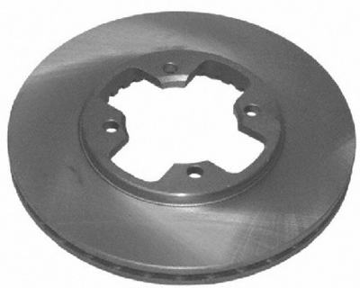
I also cannot get 4 stud discs to suit r32 brakes from DBA, they also do not offer a 2 peice disk in the required size. I will talk to the engineer if i can use a two peice rotor and machine down a 316mm dia 2 peice rotor disc to 280mm. Otherwise i'll have to source a undrilled disc and get it drilled to suit. As the disc will not be hubcentric i'll have to get a machine shop to do this as the clearance will need to be minimised, or i get a sleeve fabricate to give the hub and extra 10mm diameter. I'm hesitant to do this as a) i'll have to balance the hub b) it adds extra rotating mass (i know it's not much but every bit counts)
 
Caliper bracket isn't due until next week, i'll keep you posted
 
SUSPENSION:
I have been to 5x different wreckers over the last 2 nights after work and have had no luck finding a non-powered rack. I should be finishing early tomorrow so I'll have time to go to the local U-Pull-It and see what i can find.
 
PICS I'D LIKE
Does anyone have pics of a 1000 on 15's? preferably watanabe's? 
FYI my offsets will be different to what everyone else runs due to the disc brakes.
 
Cheers
Luke
Cheers
Luke
Good stuff Luke, at least it will be done right! So far as 15"s clearance on the full lock is to tight even with 14"s mine can't go full lock. Although you can get better profiles with 15. Do Torana's have a  rack and pinion? HB model or even lc lj? Maybe even Castlemaine rod shop or those sort of suppliers, a lot of hotrod gear is relatively small and may adapt.
DBA does a 296 x 28 VT-Z rotor in 2 piece
You could use the flat disc and make your hat to suit
 
Since the pads are held in with pins the 2mm difference in original disc thickness wouldn't be an issue
DBA5040.1S
 
https://www.mdspares.com.au/images/5443/5040_1.jpg?cache=20160620163550
def mod the tunnel as needed, any bolt on flares? wide track?
chinese t28 turbo wont have lag at 8psi 12psi 16psi will be easiest
for power ups and uses stock steel rotor seals & engineer once
 
rack some thai K used was early 80s corolla, suzi swift also good no power.
Brakes are oversized in your approach as bathurst winning 1000s outbreaked
all cars even 4 wheel disc alfas by 50 metres later into the deepest corners
that was with green grabber brake shoes on stock drums. Centre of gravity is
better with 13s max albeit less tyre choice but 13x9s all round with 254mm
diameter discs will be overkill anyways, pls rethink yor current crazy sizes!
 
my pintara discs all round never had any fade at calder (tight track) but needed diff baffles
Also you will need 4.5 to 5 to 1 diff ratio minimum with 5 sp or 6 sp with rotary
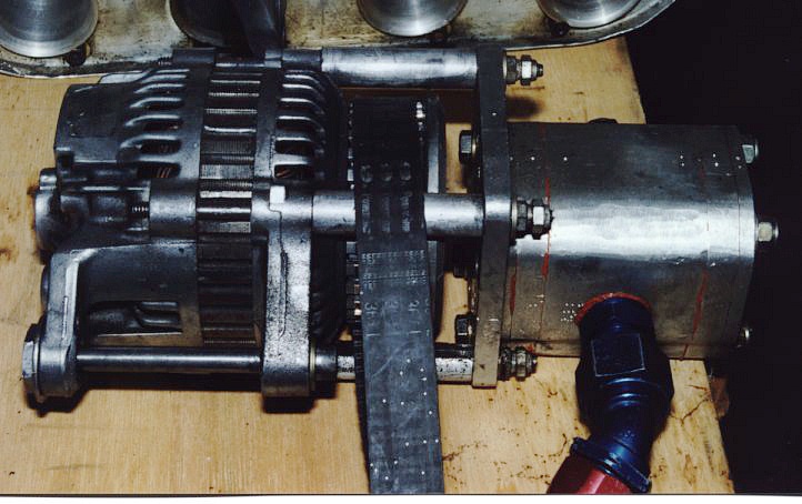
dry sump is awesome you can mount off the alternator as well
During times of universal deceit, telling the truth becomes a revolutionary act, Big Brother is watching you - George Orwell 'Most Jews do not like to admit it, but our god is Lucifer -- so I wasn't lying -- and we are his chosen people. Lucifer is very much alive.'"  Harold Rosenthal http://www.thetruthseeker.co.uk/?p=24688
I did have a nice long post that for some reason didn't go through
 
short of it was
 
I'm picking up a Toyota Starlet rack tomorrow, it's the shortest (and has the smallest diameter) of anything i have seen so far
 
overall diameter between 13's-15's isn't much as the 13's are usually a 60 profile, while 15's come in a 50 profile (and a few in 45)
 
standard gaurds for now, likely will increase track width once i fit a turbo
 
was planning on either T28 or titanium wheeled turbo from a TME 6.5 Evo
 
Brakes are overkill. If you can recommend a 4 pot front caliper with a smaller disc that would be great. I know a RX7 one has been used under 13's but i can't find any info (just a pic)

 
I like the simplicity of a single belt, but i'll have to see if the required ratios between the sump pump and alternator are even remotely close to each other.
 
Cheers
Luke
Cheers
Luke
Those volvo calipers are too heavy
If you use the RX7 S4-6 caliper its lighter alloy and a thinner disc.. less rotating mass
Then you can pick up a 2 piece disc more like what your after
Evo 4 rotor is 294mm x 24mm  thick which would be nice 
Just needs a hat made
DBA5417.1S
 
Neils the man for the brakes and worth talking to the owner of
1000 coupe what was campaigned by Steve Newing and then
sold to that datsun mob in Sydney that do A series engines and
developed the car further before it came back to melbourne
and got wrecked by stisux or whatever his name is on 1200.com
Here is one using the 280zx front and rears which are 252mm
and consider thats stopping a car double the weight of the K.
I remember Newings 1000 having 25X mm vented rotors
and no need for alloy hats as design is super light efficient
keeping it very simple like the 1K design (S12 also have same design)


that had the late S4-6 mazda calipers on discs that sat in 13 inch wheels
60 profile tyres suit the relatively antique suspension of the 1000 yet I had
13 inche 50 series as well which were awesome made by Toyo and later
changed them with yokohama equivalents 175/50/13s are were fantastic
slightly stretched over 6.5 inch rims that sat nicely on lipped guards
there are heaps available from Japanese manufacturers.

http://bullmotifminispares.com/images/products/large/QTYR011.jpg
http://www.demon-tweeks.co.uk/motorsport/competition-tyres/yokohama-advan-a048-r-tyre
 
Im pretty sure a datsun 1000 coupe by the rat 1k ute owner which is a show car hill climber
has them on 13 inch superlites and worth talking to him as he is a 1K freak and can help
with his views on the mazda caliper, rotors and tyre combo he uses for a hillclimb record
 
I think these are 175/60/13s n 13 x 8 rims a bit too much but they work on drift cars
without damaging anything but the rims when contact is made on unwanted things
http://www.outuvit.com/sozsei/Outuvitians/Chuck/ATSrocco/ChuckATS13x8.jpg
During times of universal deceit, telling the truth becomes a revolutionary act, Big Brother is watching you - George Orwell 'Most Jews do not like to admit it, but our god is Lucifer -- so I wasn't lying -- and we are his chosen people. Lucifer is very much alive.'"  Harold Rosenthal http://www.thetruthseeker.co.uk/?p=24688
Neil,
The R32 GTS-T ones are also 4 pot alloy calipers, It would be cheaper for me to just get them machined to suit a narrower disk, I was thinking the 280x21 Mazda MX5 Goodwin upgrade (DBA52545.1) or thinner still the 277.8x15.9 formula 3 discs (DBA5003.1)
 
Rear could then be a 254x9.5 disc (DBA42999) as opposed the the usual 258x9 S13/14/15 rear
 
d,
If someone could confirm that the S4-6 calipers will work on a S12 disc (250dia) let me know as the R32 ones will likely be too big.
Is this 'the rat' on the forum? Would like to get some info about suspension set-up as well as on brakes.
 
 
I'll post an update either tomorrow night or Monday after work
But here is a teaser
 
Cheers
Luke
Time for an update;
 
MOTOR
I finshed re threading the last of the bolts so i bolted the irons and rotor housing together 

I then placed it in the engine bay and sat a T25 turbo and a alternator (note from a Starlet) in there as well

Everything fits, but it's very tight.
Which leads on onto...
 
STEERING
So I went to the wreckers and picked up a Toyota Starlet steering rack as it was the smallest manual rack that they had.

I placed it in the engine bay and immediately noticed that if i shorten the rack the steering column would want to chare the same space as the motor...

So plan B it is.
I'll keep the length of the rack the same and change where the tie rod mount, same as what this Flaming River steering rack does

 
I then positioned the steering rack so that it would work with the externally mounted tie rods and placed the motor in the bay as well

It was looking promising, until i went to position the turbo...

The turbo wouldn't fit as the steering column was in the way
 
I initially tried many different ways to mount the steering rack in line with the pivot points, exactly like the flaming river example above. But kept running into the same issue.

 
It did give me the exact spot where the knucles on the steering column would have to sit for everything to line up, so i want back to the wreckers the next day to find a suitable length upper steering column. Turns out the Starlet is a pretty close match, it's about 100mm shorter then i would have liked (I initially measured it at only 50mm short but the airbag steering wheel took up 50mm...). I figure this can be taken up by a deep dish steering wheel and a quick release hub (or boss kit depending on engineers willingness to pass a quick release hub)

Also that previous night it hit me that because the tie rod mounting points are external there is no reason for the steering rack to be aligned with the pivot points, i can position the external linkage in a way that does this for me. Opening up about a million other steering rack locations.
 
After many more hours (around 5) of playing around with steering rack positions and engine (and turbo) positions i found one that worked.
I raised the steering rack as high as i could (so the moving section of the rack was almost touching the chassis rails) and positioned the output shaft as close to the chassis rails as possible. This moved the steering linkage almost directly over the chassis rails, there was no way i could have possible made more room for the turbo...

And the results (ignore the 10mm plate, it was all i had that was thick enough to space everything out properly, while still being able to tack things in place). Note the compressor housing does fit but kept falling off while tring to take a photo (as the circlip has been removed so i could rotate the housing as required)

Better yet it also lengthed the steering column by about 20-30mm from where I measured it yesterday
 
The only downside is that the engine is now sitting on top of the steering rack (about 50-60mm higher then i'd like) making the centre line of the gearbox sitting almost on the gearbox tunnel. 
To remedy this i'll have to move the engine back by around 30mm, by enlarging around the firewall/gearbox tunnel join.

(note the 15mm was if the steering rack or engine could be moved further apart, it may have just snuck in)

The down side is that the motor and gearbox will have to be installed/removed as a single unit from underneath the car (ie they can't be split in the car). considering it's currently sitting about 30mm higher then when wheels are attached and i can just fit the motor under the cross memeber and lower rad support, i don't think this is a big issue.
 
Oh and some more pics as to why i decided to go dry sump (from a clearance point of view)


Keep in mind I already have to move the engine back 30mm, with the standard front cover it would be over 140mm, and then i'd still have clearance issues with the sump and the engine would have to sit higher or the sump would scrape.
 
Plan for this week is to 
a) hopefully get the prototype brake adaptor plate back from the machine shop
b) pick up gearbox
c) make brackets to secure the steering rack
d) make the external adaptor for tie rods
e) properly mount steering column (and cut off all the unused brackets)
f) mount pedal box (once steering column is mounted)
 
Does anyone know of an alternate tie rod end that has the same taper?
I'm going to have to machine down the tie rod so i might as well get something off the shelf (as opposed to the $120ea people are asking on ebay)
 
Cheers
Luke
Cheers
Luke
http://datsun1200.com/userinfo.php?uid=5158
 
G,day D give me a call on nine7five8nine5zero1
It is easier than using (bloody computers)
 
A14 1000 coupe road car
A15 1000 coupe race car
A10 1000 ute mat black (rat ute)
1000 wagon 4age 20 valve(next project)
During times of universal deceit, telling the truth becomes a revolutionary act, Big Brother is watching you - George Orwell 'Most Jews do not like to admit it, but our god is Lucifer -- so I wasn't lying -- and we are his chosen people. Lucifer is very much alive.'"  Harold Rosenthal http://www.thetruthseeker.co.uk/?p=24688
D,
I sent you a PM, I'll give u a call later in the week about catching up for a beer.
 
Unfortunately I didn't get as much done this weekend as I would have liked due to my legs falling off (not literally falling off, just very sore from the first week back at footy training)
I got the one half of the steering rack mounted. It's nice and solid, gave it a solid hit with a hammer and it didn't move... then i added some more bracing for good measure.

I'll need to scavange the other half of the bracket from another car at the local u-pull-it. Failing that I'll have to bend the edges in a vice with a hammer to add the required strength
 
I also got the steering column mounted (no more cable ties), although the height may change depending on my final seating position

 
And because my legs couldn't handle staning up for much longer, bending over the front rad support, i also cleaned up the toe rods (no before pics). Everything was heavily rusted and it took a lot of yield (basically the holy grail of WD40 type products), and even more choice words to get the nuts off. The sleeve that sits under the bushing was almost fused to the threaded rod and had to be cut off. I ran over the threads with a die nut and it's as good as new.
 
 
And the obligatory shot of the engine in the engine bay (note the missing rear iron as i'm not cutting the firewall/gearbox tunnel until i choose/pick up a gearbox)

 
Given the tight clearances I'm going to have to mount the turbo, alternator and oil pump before i can position the engine in a final location. Speaking of this came in the mail...
 

It has one more stage then i require, but i'm not sure if i want to cut it down yet. If i do i'll remake the mount as well to cut the size (and weight) down dramatically. Either way i'll be stripping it down, cleaning it out and replacing the seals.
 
 
An issue I overlooked previously is that i'll be bolting the turbo directly to the exhaust port of the engine. I can cut a flange and get it welded in place of the current T2 flange on the mock up T25 turbo, but from those that know much about rotary engines the exhasut gasses can reach up to 1100C (yes that's not a typo) so either a titanium or inconel exhaust wheel needs to be used.
Also look at the pictures below of the exhaust sleeve, it goes from an oval to a circle

This is all well and good when trying to match it to a round exhaust manifold, but the turbo's intake is also oval shaped. It's also well known that the opening expands too quickly resulting in a loss of velocity of the exhasut gasses.
This will therefore require a custom made sleeve that adapts from the oval opening of the port to the oval shaped turbo flange to take the most advantage of both the velocity and heat produced by the motor (thereby reducing spool). This again needs to be made from either inconel or titanium
 
As the clearance is so tight between the turbo and steering column I'll have to get the turbo i'm going to use, properly in place, before I can make engine mounts as if it's off by even 5mm i could run into issues. So I'll likley have to wait a few weeks for the turbo to be fabricated... If anyone knows anywhere that sell titanium or inconel exhasut wheels let me know.
 
At this stage i'm not 100% sure if the engine, etc will be run in the centre of the car, I may have to offset it 10-15mm to allow for enough clearance. I know the steering linkage cannot get any closer to the chassis rails (it rubs a little atm, but nothing a well placed hammer hit can't fix), so there isn't much more i can do.
 
I'm hoping this shouldn't hold me up providing that i can get my hands on either a gearbox or rear axle this weekend. Although I also have a heap of body work to do .
 
 
On a better note I have found something interesting...
As my front iron is brand new it's not stamped by Mazda with a engine number, hence the year of manufactuer is unknown. The 6 ports rotaries started in '81 so I could claim the plate/engine is as old as that, but providing it's before '86 (which the 13b 6 port started in '84) there is a nice little clause in ADR27A/B/C which i'm hoping I can exploit...


1.   All passenger cars and derivatives equipped with petrol fuelled spark ignition internal combustion engines manufactured on and after 1 January 1982, except those with an engine displacement less than 850 millilitres, are required to comply with Australian Design Rule No. 27B - Vehicle Emission Control.
 
Seeing as the engine displaces 664cc (664mL) I may be exempt from emissions. I have run this past the engineer and am awaiting a responce. This would not only mean i don't have a $400ish emissions inspection fee, but i don't need to run cat or any other emissions gear.
I'm not sure how this applies to the noise requirements as they are also part of the same ADR.
Cheers
Luke
Rocher maybe Im confused but Josh from Adelaide
bought my single rotor setup and my white vb10 wagon
came over to Melbourne with brother and took off again
with vb10 + rotor on trailer behind a v8 commo ute
Are you one of these brothers thats moved to melbourne
or is this a totally different project to those boys?
apologies for my misunderstandings but Im in Japan now
no longer in Melb but Mark is and is the 1000
king of Melbourne for those who know him and a t
op bloke as well he doesnt do inet though.
 
Another suggestion is to go PP or a you using just
one side plate to feed it? with boost you wont need
2 ports really all the simpler. You can angle grind
with a flapper disc some of the edges of the engine
all round for more clearance as well.
 
https://www.youtube.com/watch?v=asUb5gf15TU
During times of universal deceit, telling the truth becomes a revolutionary act, Big Brother is watching you - George Orwell 'Most Jews do not like to admit it, but our god is Lucifer -- so I wasn't lying -- and we are his chosen people. Lucifer is very much alive.'"  Harold Rosenthal http://www.thetruthseeker.co.uk/?p=24688
Nah that's not me. I'm building mine from scratch. 
did u buy an atkins single rotor 13b e shaft or machine down a normal one? I'm tempted to machine down a 13b on a lathe at work with the help of one of the machinists, but not sure if i trust myself enough to do the job...
 
I agree that with boost it would be easier, for more or less the same result, using a normal 4 port engine (ideally a PP, but doubt i'd get that road legal). But I want to run the engine na first so i can sort out the suspension and get used to driving it. I want to make sure i can drive the car at it's limit before i add more power so i can take advantage of it's lightness. 
 
It will take a lot of getting used to as i haven't been to the track for 3-4 years, and i didn't consider myself a 'good' driver back when i was heading out twice a month. Plus i have never run on semi-slicks or in such a light car (had a 180sx), so it will be weird braking so late into corners.
 
FYI the eventual plan will be a race spec PP turbo motor (ie no power below 7,000+rpm), but that will be a long way off. Plus i want to wait for the new Mazda rotary engine before doing a race engine as from what i have read there are going to be quite a few changes to increase thermal efficiency
 
I take it the number quoted above is Marks? If so i'll call him on Thursday or Friday. I was going to call last week, but was sick.
 
 
Oh and sorry guys no update from the weekend, i was sick so spent most of it either in bed or sleeping on the couch...
Cheers
Luke
Oh right! I got mine from an escort sports sedan who used to get around 280hp boosted
till it went to 13k rpm and flywheel rearranged the firewall and almost the legs of the owner.
That escort went from a perfect light turbo PP to a useless cleveland v8 and for sale on
105.com atm as far as I know its the only one to be weighed down like a tank
During times of universal deceit, telling the truth becomes a revolutionary act, Big Brother is watching you - George Orwell 'Most Jews do not like to admit it, but our god is Lucifer -- so I wasn't lying -- and we are his chosen people. Lucifer is very much alive.'"  Harold Rosenthal http://www.thetruthseeker.co.uk/?p=24688
UPDATE:
I picked up an RX8 gearbox friday after work so spent all day saturday hammering and cutting the trans tunnel to get it to fit

I manged to get it within around 50mm of where it had to go without cutting much (just around the firewall/trans tunnel join) and called it a day.
 
Thinking it was almost in i decided to go and pick up a datsun 1200 ute rear axle.
(no pics, you all know what they look like)
 
I figured before getting the gearbox in the last bit i would mock up the motor to ensure it was in the right spot and the that turbo would clear.... And it wasn't even close. I had to move the motor back about another 20mm and also offset it to the passenger side by 15mm to get everything to clear. It must have been bumped during the original mock-up off centre and further back.


If you look at the old photos the rotor housing was just in front of the firewall, it's now just behind. FYI the engine looks even smaller in person then in the photos
 
Moving the engine, etc back wasn't difficult as the firewall/trans tunnel had already been cut, but because i have to offset it 15mm towards the passenger side i'll have to cut out most of the trans tunnel. As a result it will be easier to fabricate a new one from scratch so i'll pick up some tube to re-inforce the floor next weekend and cut the entire tunnel out. It will also make fabricating a gearbox mount much easier. It's probably for the best as it will also allow a bit of extra room to run the exhasut. This all would have been a piece of cake if the exhaust/intake was on the opposide side of the motor... 
 
photo's of todays mock up
 

Note the dry sump pump will have one stage removed and will sit below the alternator. I'll also have to fabricate a new bracket as the old one will not work.
I could not hold the turbo and take a photo at the same time so the compressor cover is sitting in about the right spot...
 
Having the engine that little bit further back should make life interesting when fabricating an intake manifold. Also note that the turbo will be sitting right below the clutch pedal, I'm glad i went with a swing mount rather then floor mount now.
 
Note to all thinking of doing something similar. An NA motor would be very easy to get to fit (providing you run a dry sump and custom front cover) as if the engine was further forward by around 30mm (from my original mock up) you may get away without cutting the trans tunnel or firewall at all. You would likely need a small cut-out in the floor for the starter though.
 
My next concern is the engine mounts. As the engine is so far back there is a large moment (force x distance) that it needs to support. I also don't want the mount breaking if for some reason the gearbox mount fails or is removed. My preferred method is a plate along the bottom that ties in into the chassis rails. This plate could also be the sump of the motor allowing it to sit as low as possible (sump level with the floor pan). The bolt holes will be the holes drilled for the steering box. Mr Datsun decided to pre-drill them on both side for me as well 
 

I'm not sure if the engineer will allow a solidly mounted engine though, i'll have to check.
 
Plan B is some kind of heavily gussetted plate that straddles and bolts to the front cross member. I'm not sure on the method to bolt to the engine as of yet, but would likely make the front cover and sump one peice and try to integrate a boltable mount to it somehow...

Note the green is a poly bush and the orange are bolts. Side view (top right) shows the gusset and cut-out for the steering rack.
 
I'm hoping my first idea is alright with the engineer as well as it should provide the extra structual ridgidity the engineer wants as well.
 
Hopefully next weekend will see me progressing a bit quicker now that i know the gearbox tunnel needs to be completely removed. No more;
-lower car onto gearbox
-gearbox hits car
-raise car
-hammer gearbox tunner
-repeat about a billion times...
 
Cheers
Luke
Cheers
Luke

 
maybe if you make a frame with something like above you could support
your steering rack and engine support all in one also giving some extra
reinforcement to reduce any body flex and even as extra turbo support area.
Its also a bit more work but you could make a tube frame for the tunnel so
you can put some bot on covers to allow top access ect.
 
If you are prepared to engineer again its up to you but Ive raced bridged ported
and PP R100 and Rx3s in the past and not a top steerer to some of my mates
but can honestly say a single PP or 4 or 6 inlet ext port 6.5B engine in NA will
leave you wanting much more than you think. A turbo 6.5B can be tuned for
no lag with 120hp atw then you can turn the wick up as you get better or more
confident using the same turbo for up to 180hp atw depending on fuels as well.
 
Turbo PP 6.5B will be so smooth you will have no issues whatsoever
During times of universal deceit, telling the truth becomes a revolutionary act, Big Brother is watching you - George Orwell 'Most Jews do not like to admit it, but our god is Lucifer -- so I wasn't lying -- and we are his chosen people. Lucifer is very much alive.'"  Harold Rosenthal http://www.thetruthseeker.co.uk/?p=24688
44 Posts - Page: 1 | 2 | 3 | Next