
Reference Material |
||
Steering
| Steering Type | Recirculating Ball Type |
|---|---|
| Gear Ratio | 15:1 |
| Rotational Numbers | 3.4 |
| Max. Steering Angle | In: 45° |
| Out: 36°36' | |
| Gear Oil Capacity | 0.24(MP#90) |
The steering mechanism consists of the recirculating ball type robust structure and gives light handling and stable functioning. The worm gear supported with upper and lower angular contact ball bearings to the housing is meshed with the sector arm through the recirculating steel balls (60 numbers). This assembly is enclosed in an oil tight casing which caries two ball bearings at either end of the cam.
When the steering wheel is turned the tube revolves the cam, which in turn, causes the taper peg to move over a predetermined arc thus giving the rocker shaft its desired motion, connected to the rocker shaft is a steering side cross rod lever, that links up with the steering linkage.
The steering linkage is the parrallalogram system and connected to the rear side of the front axle.Two shorter side rods, one on either side, connect the steering gear arm to the steering gear and idler arms respectively.
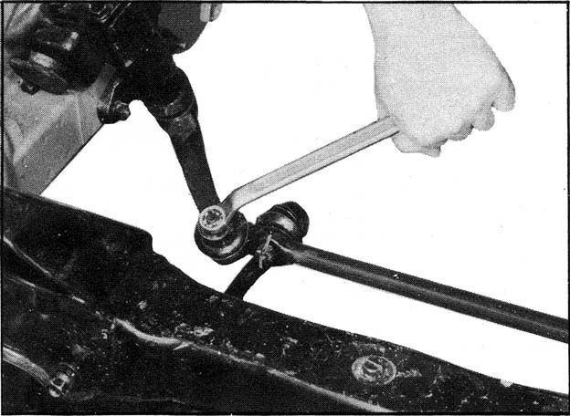
Side Rods.
The side rods are held in position by a castilated nut and split pin at each end.
To remove the rod, withdraw the split pin and release the nut at each end of the rod and then slightly tap the rods clear of the levers to which they are connected.
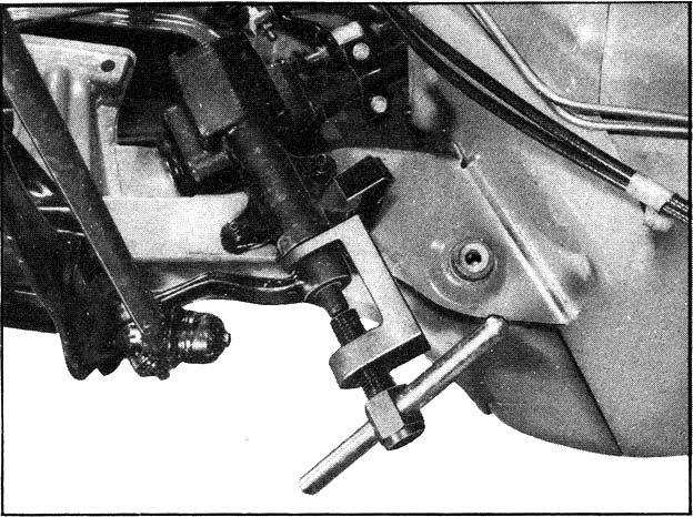
The steering gear arms and idler respectivley are attached by a nut and split pin each. Normally these levers need not be removed for any general maintenance.
The only occasion requiring the removal would be when damage has occurred, under which circumstances the steering box or under idler should also be removed for inspection when the arm concerned can be withdrawn, once the steering gear box or idler has been removed to the service bench, the gear arm should be withdrawn from the shaft concerned using a suitable extractor.
The gear arm must not be hammered from it's shaft.
After the side and cross rods are disconnected the idler can be detached from the body.
It is secured by two bolts to the front suspension crossmember.
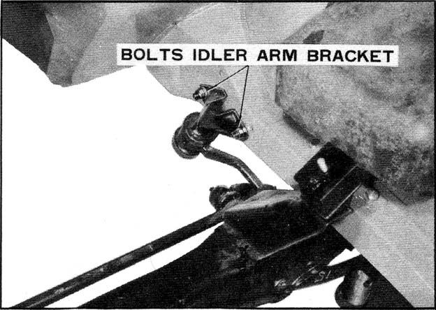
Holding the idler body on the bench, take off the rubber cover.
Pull the idler shaft out of the body.
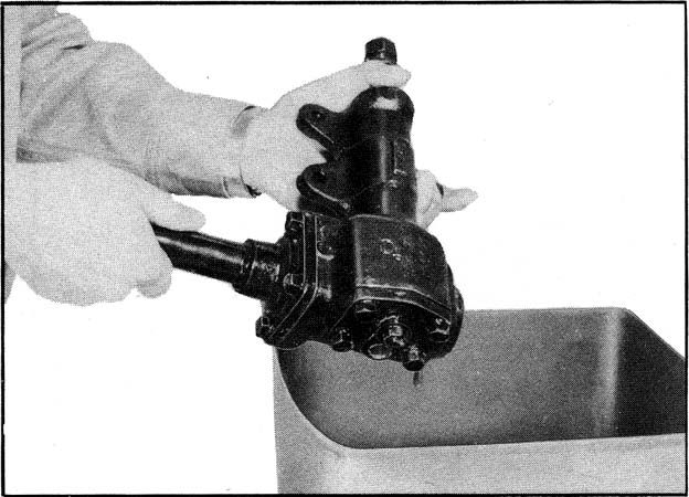
Steering Gear Housing
Disassembly
Take off the plug and drain out gear oil.
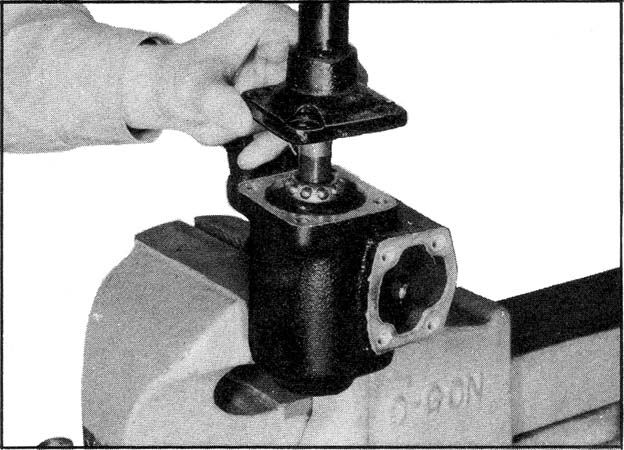
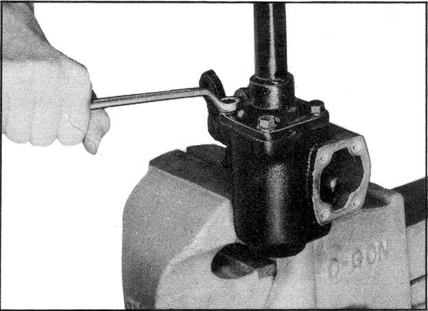
Unscrew the lock nut of adjusting screw, and take off the side cover.
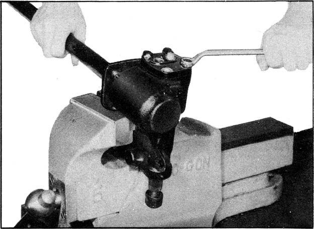
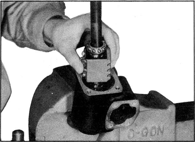
Seperate the adjusting screw and the side cover and detach the sector shaft from body.
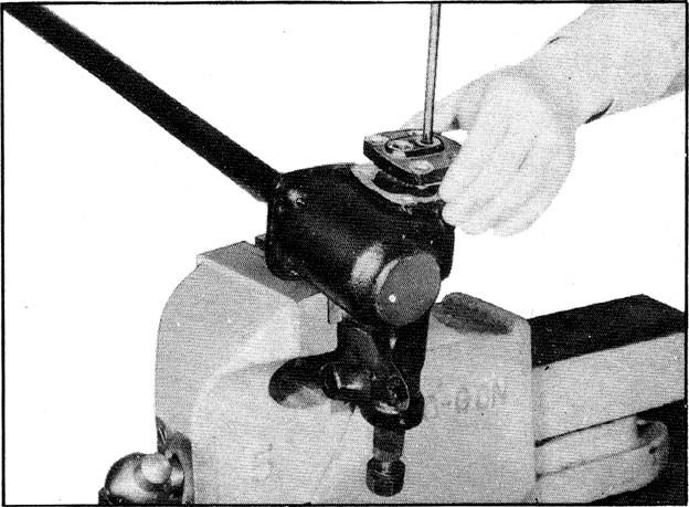
Unscrew the fixing bolts of rear cover.
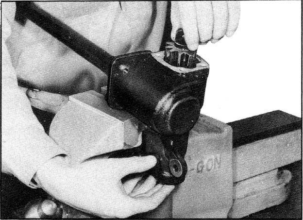
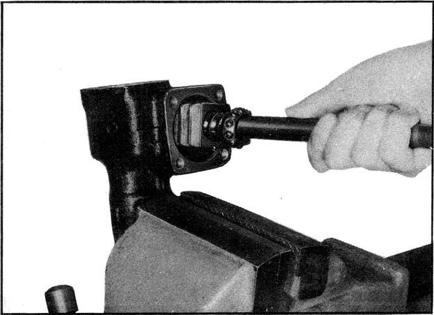
Draw out the ball nut assembly.
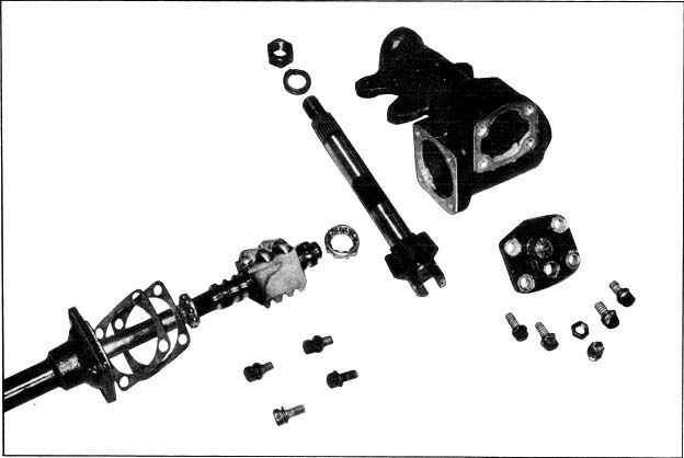
Components of Steering Gear Housing.
Assembling of steering gear housing is a reversal order of disassembly.
Assembling.
Slip the nut over the worm with the ball guide holes up and the shallow end of the rack teeth. Align the grooves in the worm and nut by sighting through the ball guide holes, count 60 balls into a suitable container. This is the proper number of balls for this ball unit.
Drop balls into each of two holes on the same side of nut. This operation may be performed from either side of nut, but two holes on the same side must be used, not two holes on same end.
Shake the nut gradually away from hole being filled. Continue untill the balls are installed in full. Plase remaining balls in ball guides, in each of two halves.
Push the guide into holes of the nut. If the guides do not push all the way down easily, tap lightly into place. Assemble the ball guide clamp to the nut, being sure to use a lock washer under the clamp screw then tighten the screw securely.
Check the assembly by rotating the nut on the worm to see that it moves freely
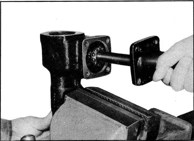
Insert the ball nut assembly with the worm bearing at rear side into the gear housing and smaer the oil to the worm bearing.
Select the same thickness of shims at the dissasembly time and connect the column assembly with it to the gear housing.
Tighten the rear cover bolts.
| Tightening Torque | |
|---|---|
| Front Rear Cover |
1.8-2.5 kg-m |

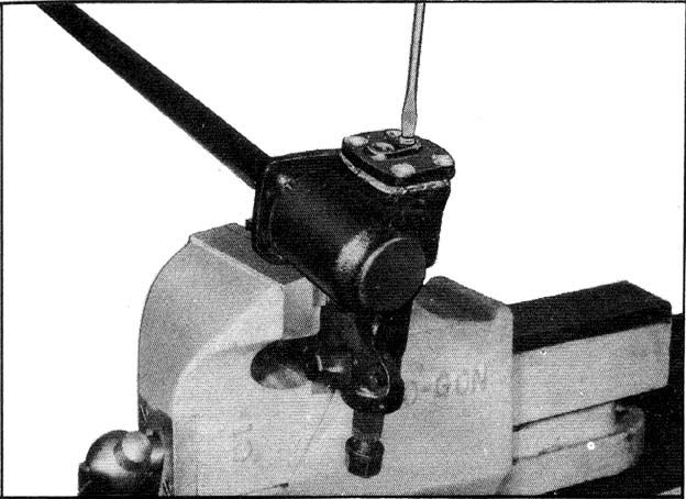
Fitting the side cover with adjust screw, fix the side cover to gear box by turning it for left way.
| Tightening Torque | |
|---|---|
| Side Cover | 1.8-2.5 kg-m |
Set up the gear arm temporarily to the shaft.
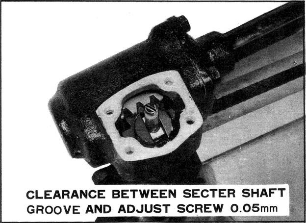
Adjust the play at the gear arm top within 0.1mm and then lock temporily by the nut.
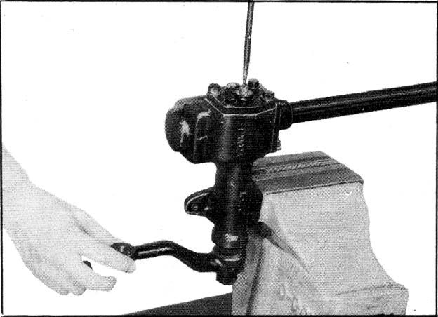
Rotating the gear arm several times for right and left way to find correct center without any variation about back-lash.
After then lock by nut surely and tighten the oil plug.
| Tightening Torque | kg-m |
|---|---|
| Connecting Bolt,Gear Box | 6 |
| Ball Stud | 3.5 - 4.9 |
| Nut, Steering Wheel | 4 - 4.5 |
| Nut, Idler Arm Bracket | 1.9 - 2.6 |
| Tie-Rod End | 3.5 - 4.9 |
